VERIFIED VIEW
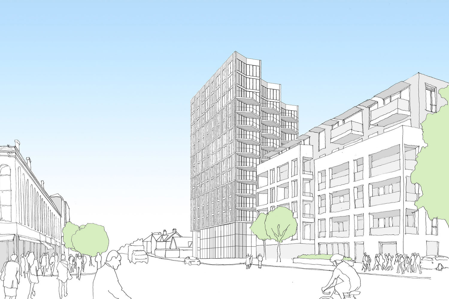
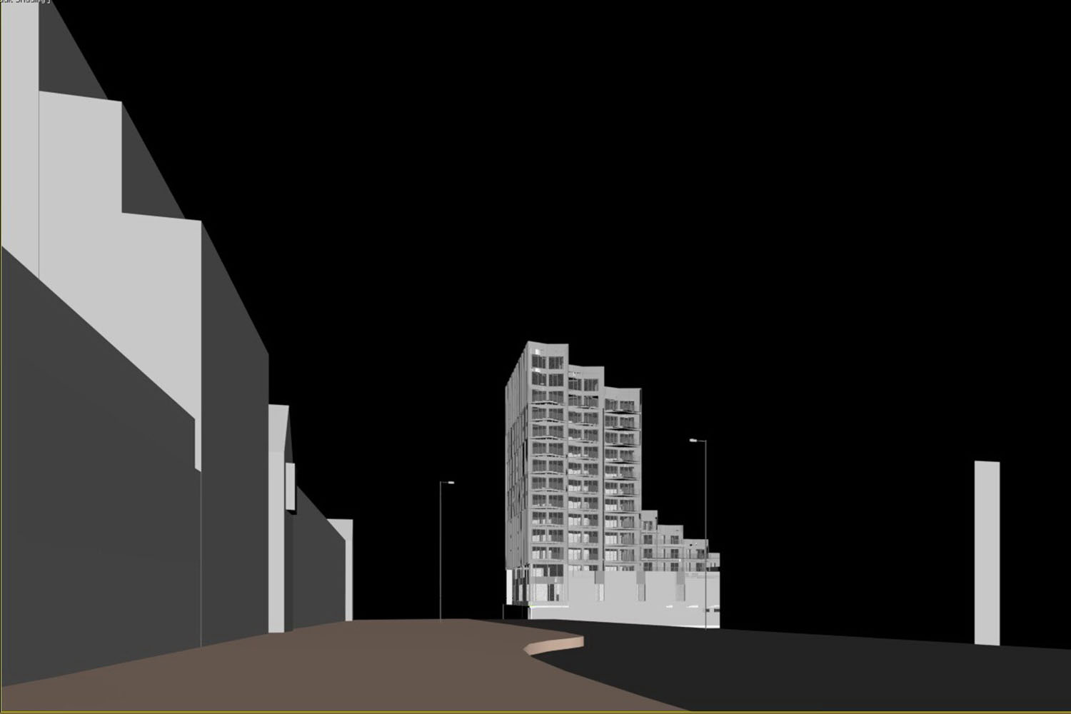
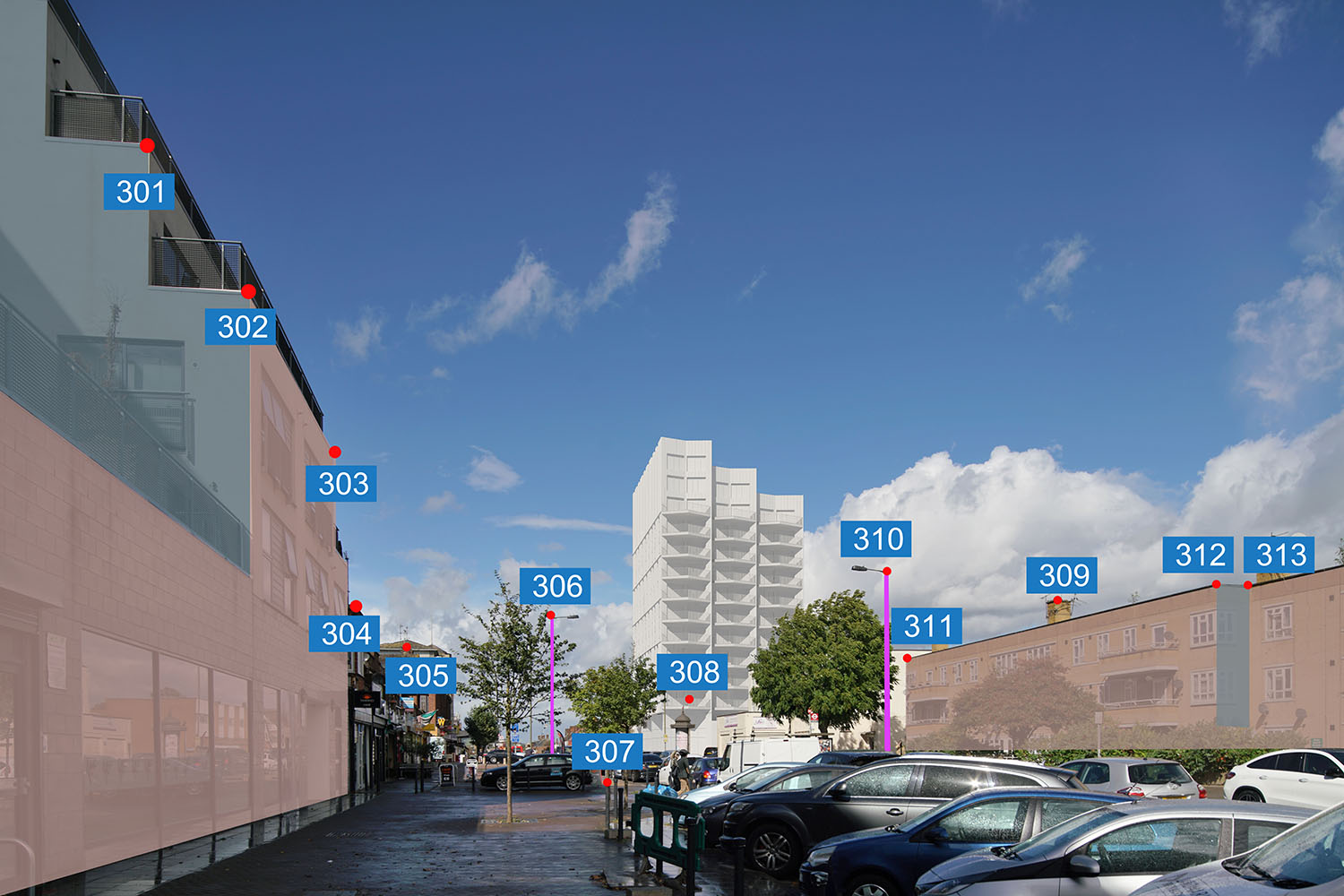
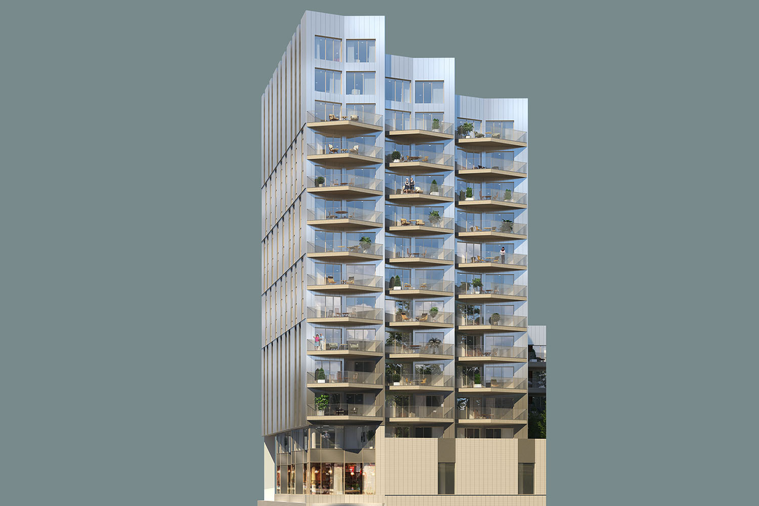
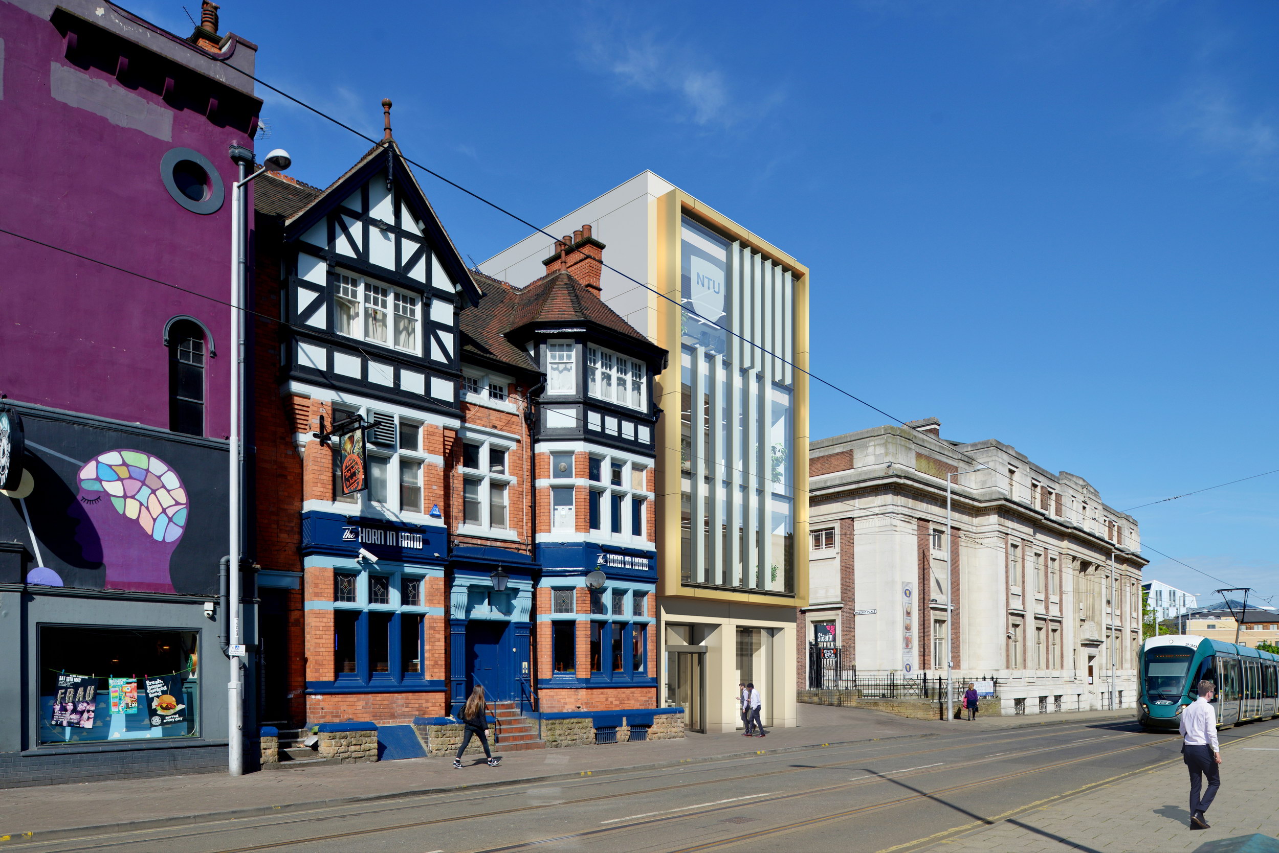
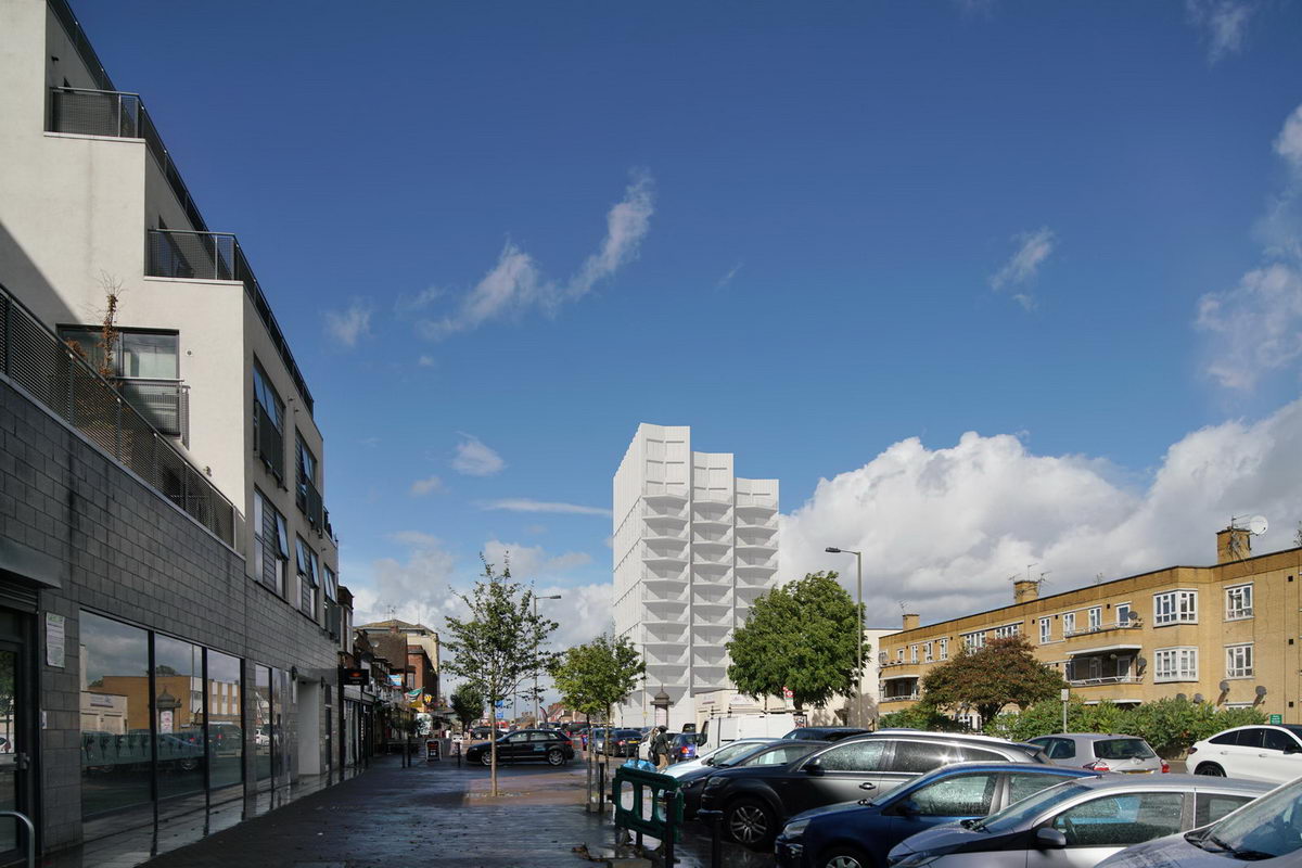
Accurate Visual Representations (AVR), or Architectural Verified Views, are highly accurate three-dimensional photomontages. We use Architectural CGI to create a precise model.
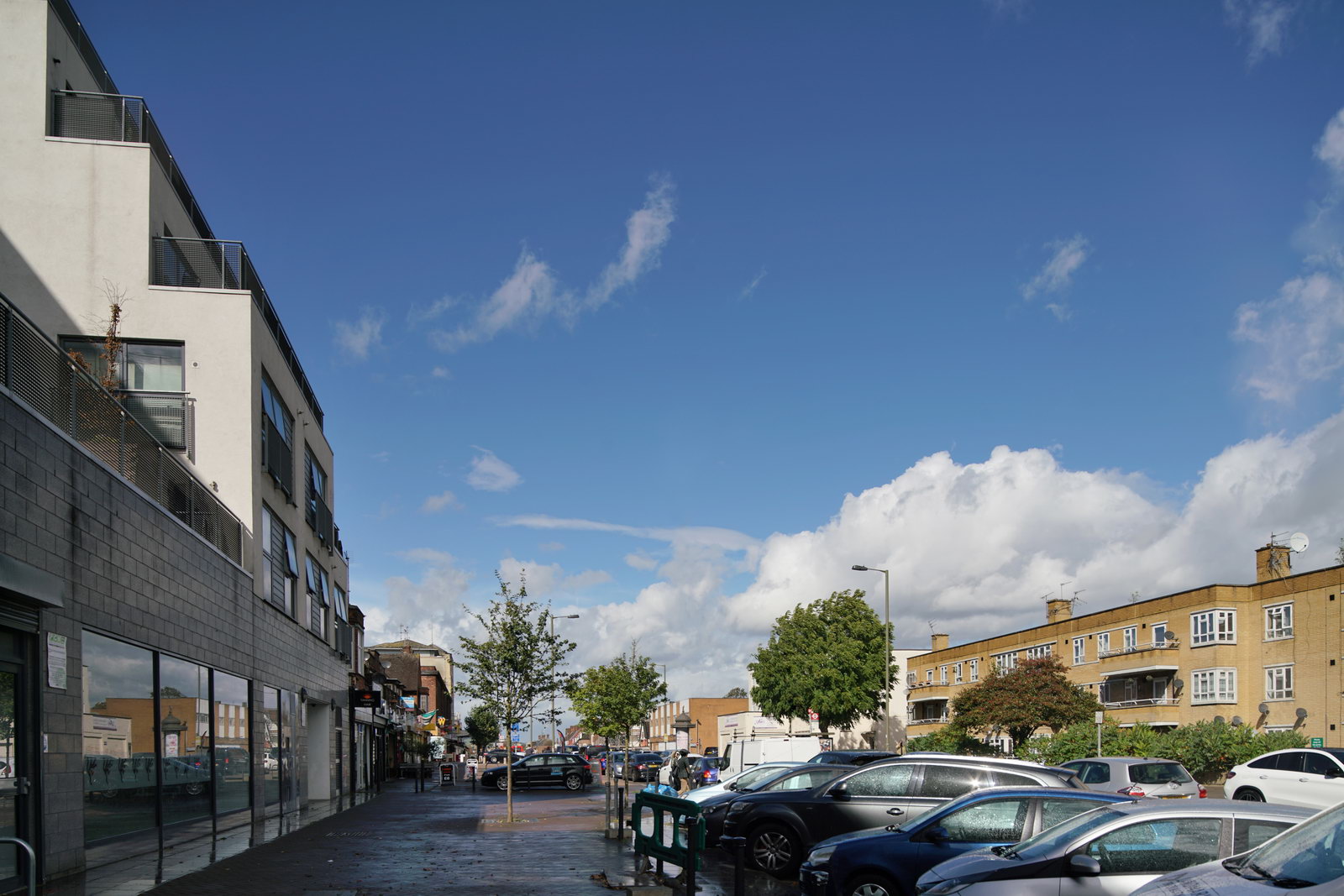
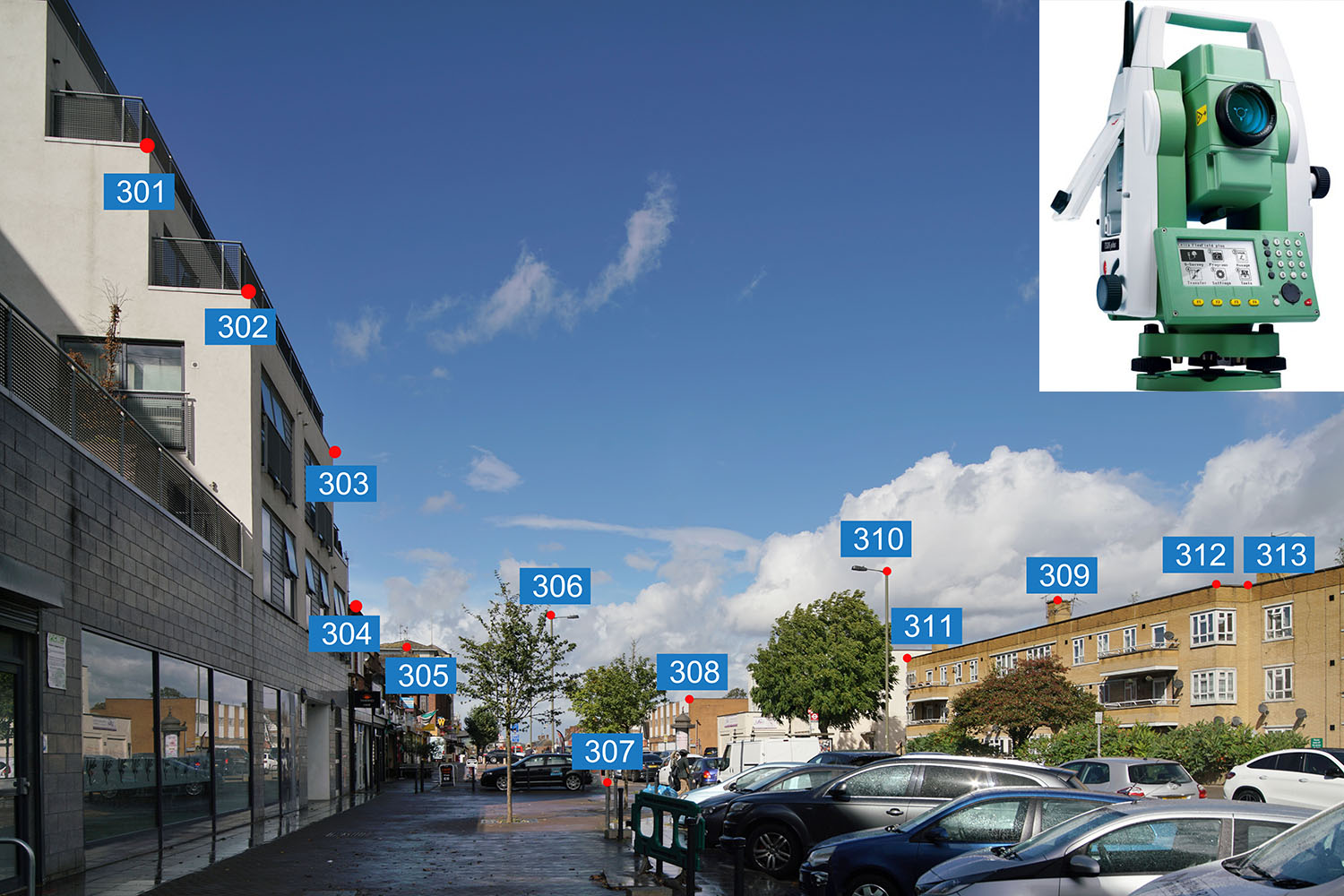
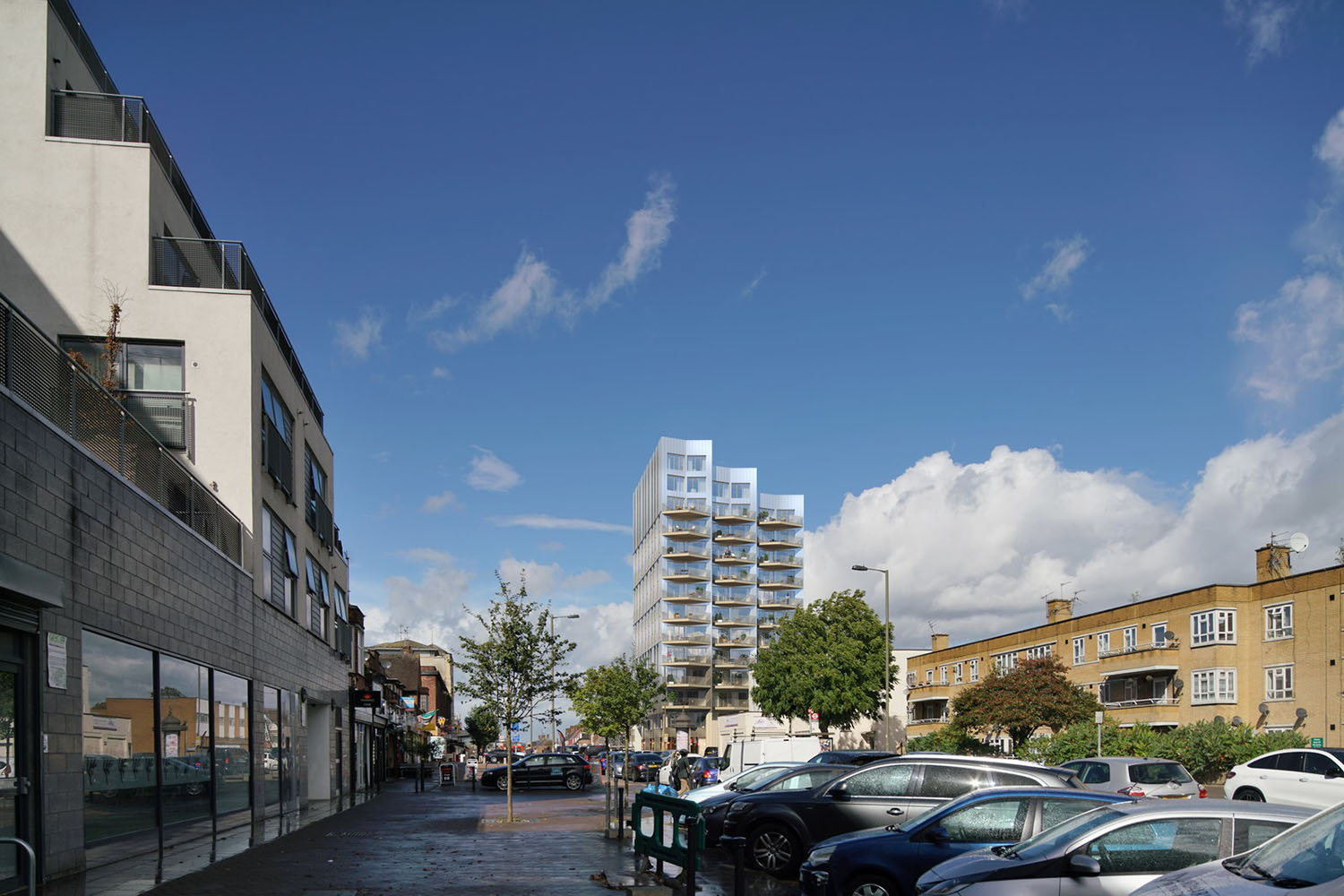
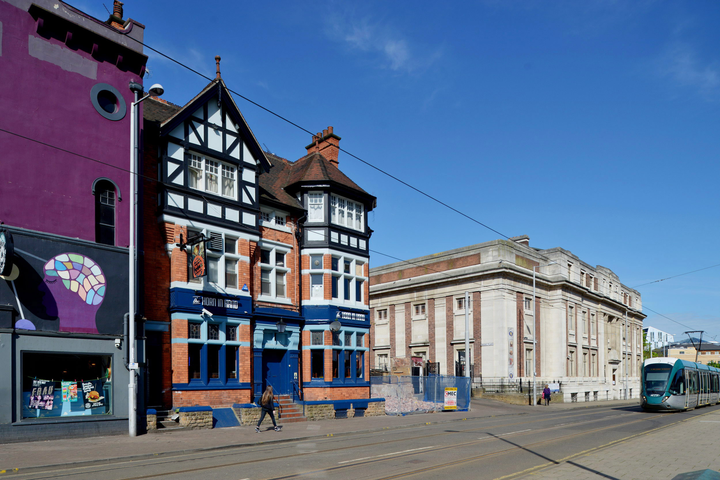
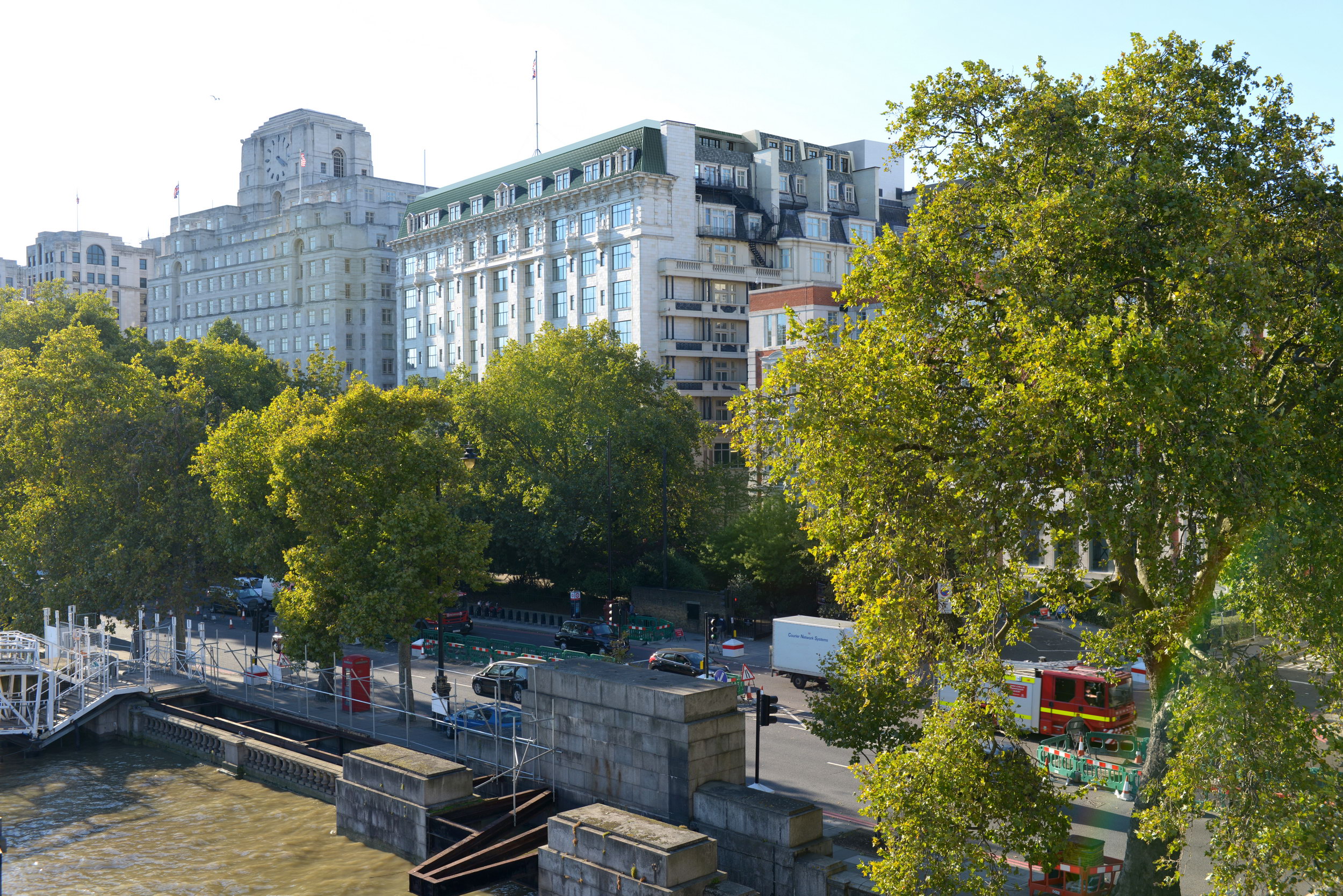
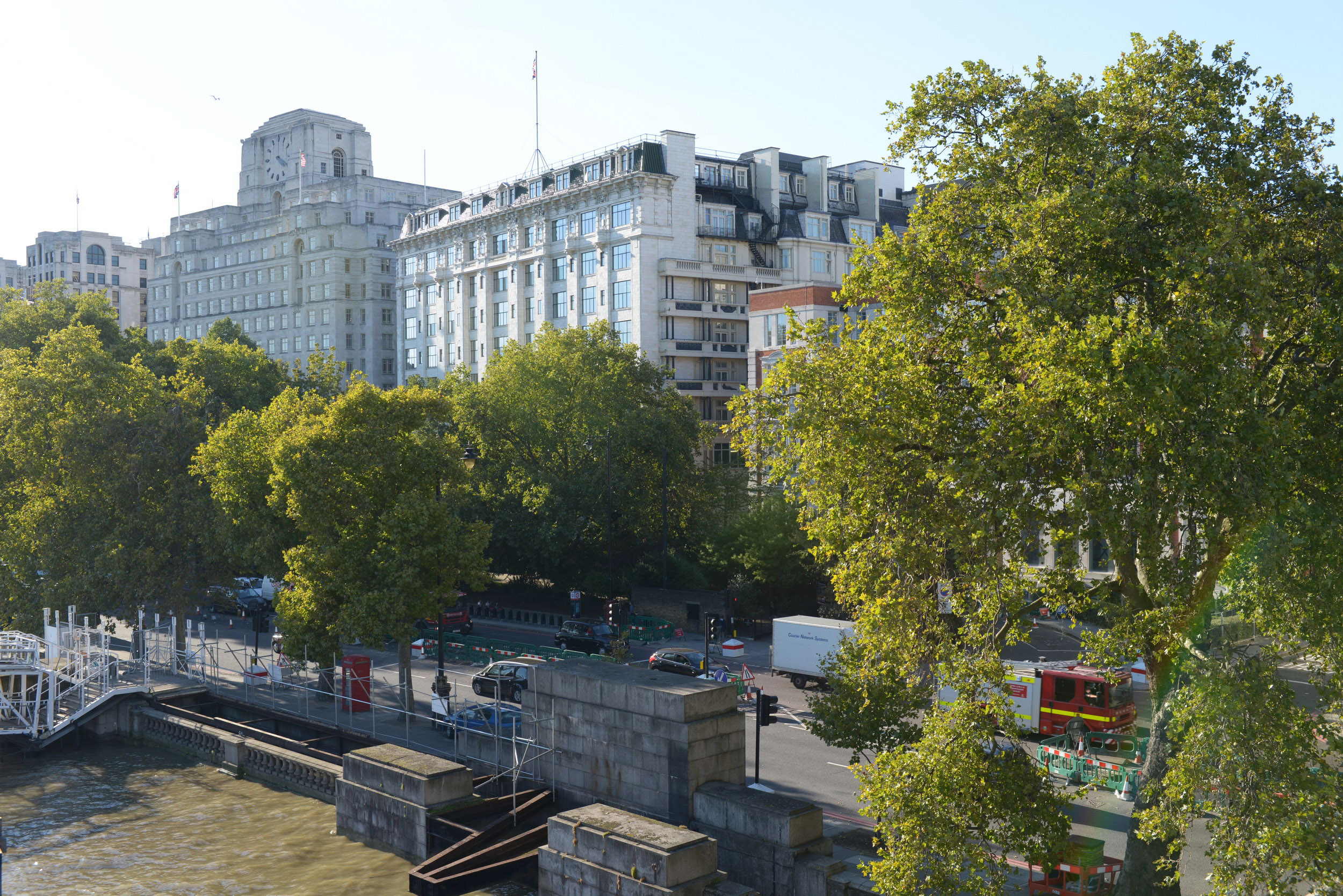
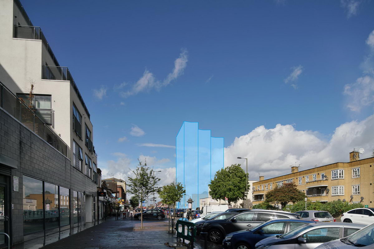
Verified views are architectural photomontages created to a high level of verifiable accuracy using accurate survey data, precise photography and a strictly recorded methodology.
Verified views can accurately illustrate the scope and impact of a development in context, so they are crucial for pre-construction planning application, public consultation and visual impact assessment, particularly for city centre schemes where the impact on the skyline is a major consideration.
We have enjoyed relationship with many UK developers and architectural institutions and supported numerous successful planning applications with our verified views. Along with high quality visualisations, we also provide a full methodology report including all the data and process by which the verified views were created.